介绍
由于激光雷达点云数据包含返回激光的任何表面的信息,we can use it to model terrain as well as building shapes.This is exactly what we set out to do in this demo,where an LAS point cloud is used to (1) build a triangular irregular network (TIN) terrain model and (2) extrude building footprints to their actual 3D height.这两个步骤中的每一个都将成为我们输出的一个层次:一个写为PDF的3D模型,它捕获了温哥华附近的城市建筑环境。
此工作流有两个技巧:(1)提取和替换建筑足迹几何图形(矢量亚搏在线数据)。以及(2)使用建筑足迹裁剪点云。简而言之,我们将隔离每个建筑足迹的点云,and then extrude these footprints into 3D solids.按照下面的逐步过程,了解有关如何设置此三维点云工作流的更多信息!亚搏在线
CAD建筑轮廓:
LAS点云:

下载
工作区说明和步骤
步骤1。读取源点云和建筑物
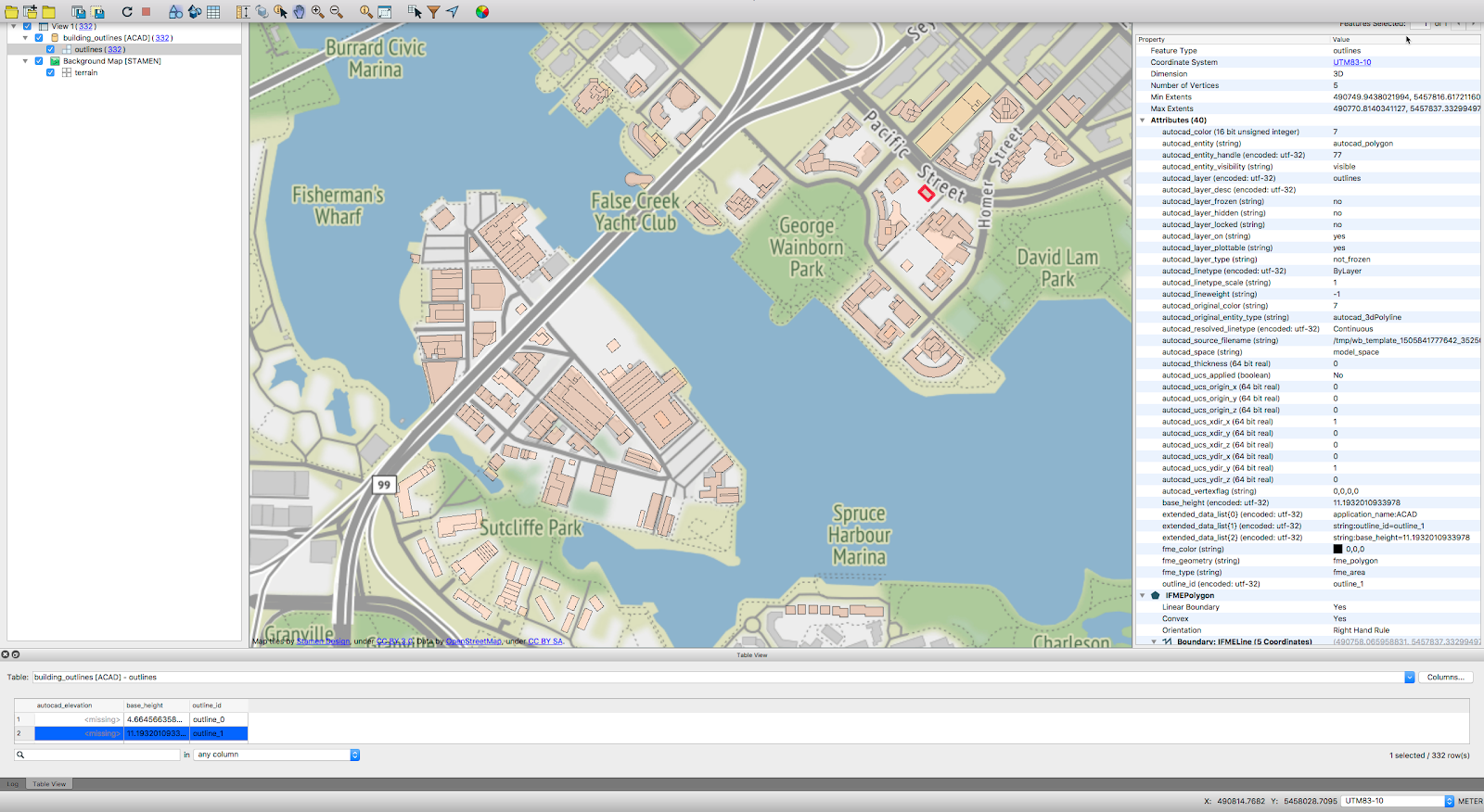
温哥华市的点云数据以ASPRS激光雷达数据交换格式(LAS)存储。三维点云的行业标准。从矢量acad dwg文件读取建筑轮廓和基准高度。读取两个文件:
source_data\LAS.laz
Add a reader for the AutoCAD DWG building footprint file.When reading in the CAD file,请记住进入参数并将“Group Entities by”:设置为'属性架构'in order to have access to the base heights attributes for extruding later.
源文件\数据\建筑\轮廓.dwg
步骤2。存储建筑几何
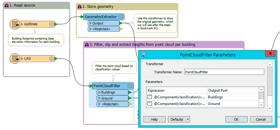
Add a几何量角器and connect the building footprints to store the current geometry in an attribute on the feature.如果必须临时更改某个特征的几何图形以获取附加信息,则此功能非常有用,在接下来的步骤中,当我们将这些数据与点云结合时,情况也是如此。提取特征的原始几何图形可以使其随时恢复。一旦我们准备好将建筑挤压成三维,我们将恢复建筑足迹的几何图形。
In the几何量角器parameters,确保几何编码设置为‘FME Binary'目标几何属性为几何体.我们不需要删除几何图形。
如果你现在想运行你的翻译,请记住调整功能处理,以便在拒绝功能时转换不会终止。您可以通过以下方式完成此操作:
导航器>工作区参数>转换>拒绝功能处理:
更改它以继续翻译。
步骤3。Filter the Point Cloud for Buildings
分类点云将包含存储分类的组件,通常作为编码数值。这种分类通常用于区分属于地面的点,植被,buildings,etc.Add a点云过滤器对于LAS读者,使用以下表达式筛选出分类为建筑物或地面的点(注意[注释]在方括号中,不包括在你的表达中)
@部件(分类)==6[建筑物港口]
@Component(classification)==2 [Ground Port]
这里是到目前为止的工作区:
步骤4。剪断建筑物旁的点云
为了得到每个建筑物的高度值,通过建筑轮廓特征剪裁点云。Add aClipperand connect the filtered Buildings points to the克里佩尔港口和建筑轮廓Clipper端口。为了保留裁剪器的属性,检查'合并属性'中的参数Clipper变压器。将“累积模式”设置为Merge Clipper',和冲突解决“使用Cclippe”.这意味着我们将保留点云(clippe)属性,并通过保留点云属性来解决合并中的任何冲突。结果是每个建筑都有一个点云!
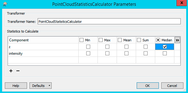
Step 5.Get Building Heights with the点云统计计算器
将内部输出端口从Clipperto a点云统计计算器变压器。Open the点云统计计算器属性并选中该框以获取每个建筑的点云的中值,并将其作为属性存储在每个功能上。使用中间带是因为屋顶提供了点云中的大部分点。我们不使用最大点云高度,因为这包括一些不代表实际建筑高度的天线。
Step 6.恢复几何图形
使用几何置换器从属性恢复几何图形的步骤几何体.现在,每个建筑都有其原始的向量几何体,并且具有从点云导出的中间高度值。
步骤7。Set Building Base Heights
因为z.中值来自点云统计计算器代表海拔高度,而不是建筑物的真实高度,we need a logical way to find the height of the building based on the two pieces of elevation data that we have: the elevation of the building footprint (base_height) and the elevation of the building rooftop (z.median).Add a3DForcerto set the base heights to the base_height attribute from the source DWG building outlines.一旦基准标高正确,我们可以用一些简单的减法精确地将建筑物的高度从建筑物的基础标高挤出到中心点云的高度。
如果您没有选择基准高度,make sure that your reader parameters are set to Group Entries By: Attribute Schema.更换读卡器以访问其他参数。
步骤8。Extrude the Buildings
An extrusion is defined as the extension of an object by an additional dimension.在我们的例子中,我们要将我们的二维建筑足迹投影到三维建筑中。为了实现这一目标,我们添加了一个挤出机 transformer to extrude the buildings by the rooftop height derived from the point clouds minus the base elevation.在中使用算术编辑器挤出机and enter the following expression in the Distance field:
@Value(z.median)-@Value(base_height)
二维建筑轮廓多边形将根据建筑的高度值成为三维实体。
步骤9。创建曲面
A surface will be created with the ground points to fill in the terrain surrounding the buildings.Add a触觉发生器变压器和接地输出端口点云过滤器到的点/线输入端口触觉发生器.的表面公差参数触觉发生器determines which input points are added as vertices to the model.在我们的例子中,值1是合适的。The larger the value,更多的输入点将被过滤掉。
Step 10.写下结果
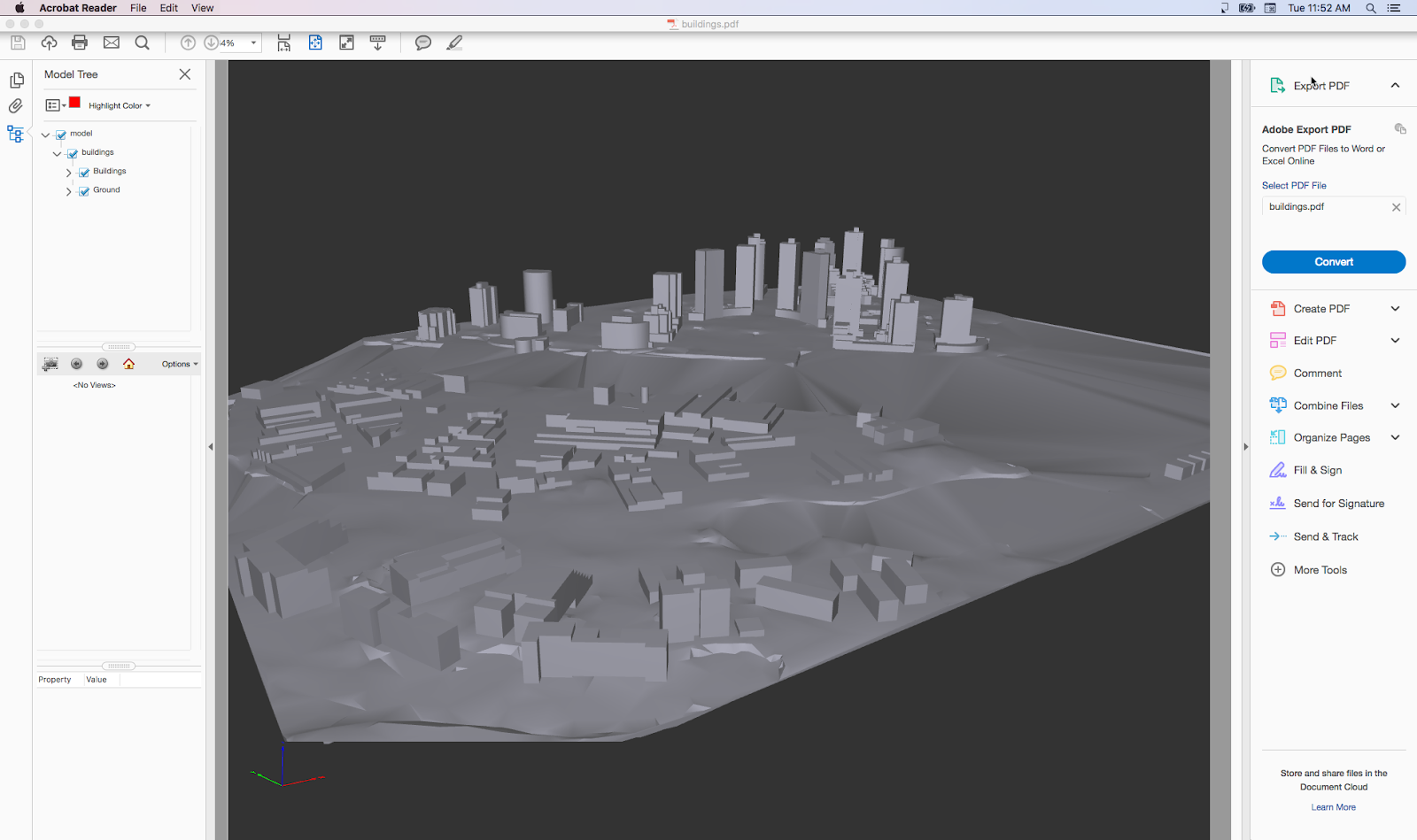
三角网曲面和拉伸的建筑可以写入任何支持曲面或网格的格式,如SketchUp,3D PDF,Autodesk FBXetc.在这个例子中,我们将写入一个Adobe3D PDF并创建两个目标功能类型,one for the building and one for the ground.将挤压过的建筑物和t表面输出端口从触觉发生器to their respective feature types.
要创建单个PDF,您将在一个编写器中写出两种功能类型:
- 连接的挤压输出端口挤出机对作家来说
- Select the TINSurface output port of the触觉发生器and go to Writers > Add Feature Type in the menu bar.命名您的功能类型并从下拉菜单中选择现有的编写器。
现在,when you go to your Navigator to view the writers,notice that there are two Feature Types in the Buildings writer.运行工作区以生成PDF文件,并使用 Adobe PDF阅读器.祝贺你!你写了332
features for outlines and 1 feature for the TIN.如果您决定进行任何更改并再次运行翻译,make sure that you have closed any open PDFs before starting the translation again.
已完成的工作区:

结果
在Adobe PDF Reader中查看的3D模型:
替代方法-从点云开始的建筑高度
If you don't have building height/elevation data present in your vector building footprints,您可以从点云数据而不是从现有属性中检索建筑物的基准高度。在挤压之前,it is best to drape the building outlines on the TIN surface.To create a flat base,应该只有一个Z每个大纲的值。为了实现这一目标,SurfaceDraper,坐标测量仪和统计计算器是一个很好的开始的地方!

Wrap-Up
此工作流突亚搏在线出显示了点云过滤器用于处理LAS文件以及FME中可能将不同类型的多个文件组合成有价值的信息产品。有了矢量构建足迹和点云,we've extracted elevation data,merged the geometries,挤压三维实体,and created a surface and building model that,一旦全部写成PDF,不熟悉地理信息系统或不使用FME桌面的同事可以很容易地在PDF阅读器中共享和查看。
数据属性
- The data used here originates from open data made available by theCity of Vancouver,不列颠哥伦比亚省。它包含根据开放政府许可证(温哥华)获得许可的信息。
相关教程:点云转换
- Current: Point Cloud to 3D Terrain Model with Buildings
- 下一步:从三维模型或光栅数据创建点云
I tried exactly the same procedure you mentioned above (minus the Buildings part).
但我没有输出,i can not visualize the 3D terrain model.我想我遗漏了一些东西,我想知道你是否能帮忙。
无论是在FME检查员还是在2016年的草图中,我都看不到任何结果。
Can you kindly advise what am I missing,请查收随附的.fmw文件
将tin导出到bim( http://www.buildingsmart-tech.org/mvd/ifc4x1/alignment/1.0/html/annex/annex-e/terrain-surface.htm) requireswhich option from the TINGenerator?
在我的第一次尝试中,我也选择了金属表面,但是,由于输出选项的存在,阅读网站可能是三角形的。
任何帮助都可以重新获得。谢谢!