介绍
点云数据通过点提供非均匀覆盖,而光栅图像使用像素显示区域的完全覆盖。将点云转换为网格化的光栅,可以方便地使用包含大量信息的数据。使用FME,you can convert a point cloud to a raster and customize your raster image by adjusting factors like pixel resolution or which point cloud component to display.The following exercises take you through different 亚搏在线workflows step by step and explain how FME transformers can be used in different point cloud to raster translation scenarios.
1。点云到灰度光栅
下载
This 亚搏在线workflow will focus on using the point cloud component called intensity to create a raster output.Intensity is a quantitative indicator of the reflectivity of an object or how "bright" the return was during the point cloud data collection.For example,植被具有较高的反射率,将返回高强度值,而路面或屋顶具有较低的反射率,将返回低强度值。如果我们只使用强度来可视化点云,we can create a grayscale raster.
- 添加点云文件LAS阅读器使用默认参数。
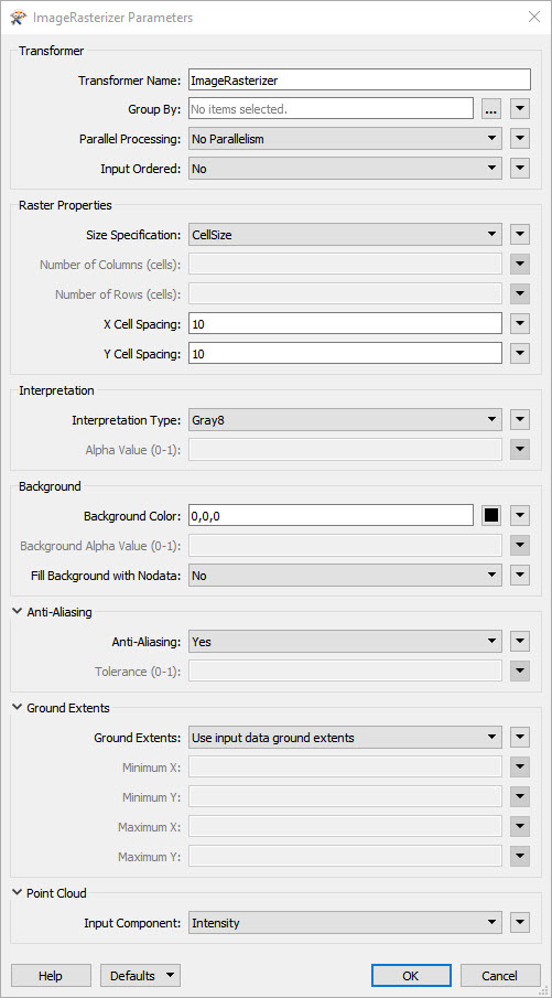
- 添加图像扫描仪变压器并将LAS读卡器连接到输入端口。The parameters should be changed so that:
- Size Specification: CellSize
- X单元格间距:10
- Y单元格间距:10
- Interpretation Type: Gray8
- 背景色:0,0,0
- 消除混叠:是
- 输入分量:强度
- At this point,a grayscale raster can be created using aGeoTIFF writer使用默认参数或更多变压器可以添加到工作流中,以进一步平滑光栅,如下面的步骤所示。亚搏在线
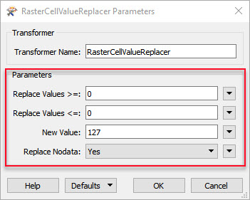
- 将光栅从图像光栅化器连接到RasterCellValue替换器转换并将参数更改为下图中显示的参数,其中“replace values>=”和“replace values<=”均设置为0,“新值”设置为127“,and "Replace Nodata" is set to Yes.This helps to remove some of the noise present in the raster image.这种平滑算法的缺点是锐度降低,因为现在像素值之间的对比度更低,因为我们已经用127(深灰色)替换了值0(黑色)。The smoothing effect is less effective in areas with many bright pixels because they have values high above 127,so there is still an obvious contrast between the ‘holes' and their surroundings.
- 将上一个输出连接到光栅扫描仪transformer and set the "Size Specification" parameter to "Percentage" with a Percentage of 101 and set "Interpolation Type" as "Bicubic".
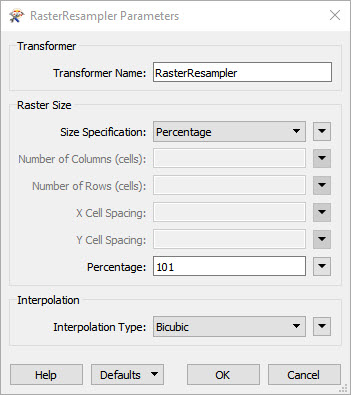
- 复制rasterresampler并将其粘贴到工作区中。Change the set percentage of the second RasterResampler from 101 to 99.001 and connect it to the first RasterResampler transformer.
- 现在可以使用geotiff编写器使用默认参数编写平滑的光栅输出。改变特性类型定义“手册”。当新窗口出现时,change "Compression Method" to "Pack Bits" and "Photometric Interpretation" to "MinIsBlack".


The result is a grayscale image.下面,from left to right are the source LAS file,rough output raster,平滑的输出光栅


输出图像通常会有一些节点数据点,比如有一个水体的地方。在我们的例子中,由于点之间的距离大于光栅化间距,因此我们有一些节点数据点缺少覆盖。In the image below you can see where there are spots of NoData:

如果有许多这样的点,或者如果输出主要由nodata组成,考虑使用更大的光栅化间距,如20米而不是10米(间距在图像光栅化器中设置)。如果节点数据像素很少,尝试使用平滑算法,例如使用rasterresampler上下重采样,as seen in steps 5-6 above.模板工作区。
2。Point Cloud To DEM Raster
下载
数字放大器使用Z坐标从点云生成DEM。The output will be effective so long as the assigned cell spacing is larger than possible irregular gaps in the point coverage.Due to the nature of point cloud data,这些差距非常频繁,因此,我们应该设置10米的大单元间距,以避免DEM覆盖中出现节点孔。我们不能像前一个例子中的强度那样使用平滑,因为它会扭曲表面,使其看起来像是被陨石击中。
- 添加一个LAS读卡器。
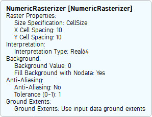
- 只需将LAS读卡器连接到数字转换器,即可创建光栅输出。下面的图片显示了在我们的示例中,numericroster所需的参数。将“大小规格”设置为“cellsize”,“X单元格间距”和“Y单元格间距”分别为10和1。Try changing the cell spacing from 10 to 2 and compare the outputs.You will find that a spacing of 2 meters will result in many spaces:
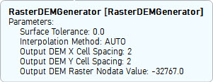
- A better option for rasterizing point clouds by elevation is the表面模数转换器或光栅发生器.Both transformers can be used in the same way,然而,SurfaceModeler具有生成轮廓或罐头等附加功能。我们选择在这个例子中使用RasterDemGenerator。RASTERDEMgenerator与numericroster生成相同的DEM,然而,it has more intelligence under the hood and is able to interpolate holes giving much smoother output even with small spacing.The parameters required for the RasterDEMGenerator in our example are shown in the image below."Surface Tolerance" is set to 0.0,“输出DEM X单元间距”和“输出DEM Y单元间距”均设置为2。
- Run the workspace with Feature Caching and inspect the output of the NumericRasterizer and the RasterDEMGenerator.


下图显示了原始点云,由数字衰减器产生的光栅(间隔10米)。以及RasterDemGenerator分别生成的光栅:


Data Attribution
- 第一个练习的数据来源于Ohio Geographically Referenced Information Program.The GIS Support Center maintains enterprise and site licenses for commercial data sets that are supportive of the Ohio Enterprise.
- 第二个练习的数据来源于西弗吉尼亚景观.They are sponsored by AmericaView and the USGS.
i tried your "Scenario11_PC2Numeric_FME2011.fmwt" and it did not work with my .LAS file !!!
我试过你的“情景11”。PC2Grayscale“附件
一切顺利,问题是,我想根据强度以颜色显示光栅…这是我对点云唯一的分类。
我应该在图像光栅跨音速设置中更改什么以获得颜色输出?
Regards,
海卡尔Intensity makes a greyscale.If you want a colour raster as your output you will need to map the intensity to RGB values.请将您的数据和工作区发送给我们的支持团队,他们将乐于提供进一步的帮助。https://support.亚搏在线safe.com/knowledgeSubmitCase