Combining CAD and GIS data types isn’t a straightforward task. It’s like the first time we try to make a rainbow by mixing all our paint together. Frayed paintbrush in one hand, dazzling array of colours in the other, we have the best of intentions. But instead of a rainbow, we get a mess of ugly brown goo.
Like the array of colours, CAD and GIS data types are dazzling on their own. But without considering proper design and structure, all we get for combining them is ugly brown goo that was supposed to be an integrated map of Downtown Vancouver.
We aren’t wrong in thinking integrating CAD and GIS can result in a masterpiece.Transformations between the two data types is such a common endeavourthat it even warrants more than one post. Today we’re going to focus on moving data from CAD into GIS. Read aboutconverting GIS to CADin part 2, andround-tripping GIS and CADin part 3.
CAD and GIS basics
 CAD, or “computer-aided drafting”, is a data type specially designed for engineers, architects, and anyone else focused on drawing with clarity and precision. In fact, I’m pretty sureTony Starkis a big CAD fan1. CAD formats involve concepts like styles, symbology, dimensions, labels, and specific geometries like splines and blocks/cells. Example formats include AutoCAD DWG and MicroStation DGN.
GIS, or “geographic information systems”, was created for mapping and analyzing geographic features. It uses location and imagery and usually conveys data on a large scale. GIS formats involve concepts like data models, attributes, simple geometries, and domains. Example formats include Esri Shapefile, Esri Geodatabase, and GML.
_____
1 Probably not true, but you never know. Jarvis is one of life’s great mysteries.
Why translate from CAD to GIS?
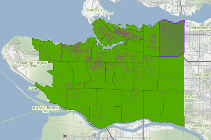
Translating from CAD to GIS means enhancing CAD drawings with spatial information and attributes.It means you can know where objects in the drawing are located as well as all their relevant details. It also meansinserting specialized CAD information into a different data structure, one that supports attribute information.
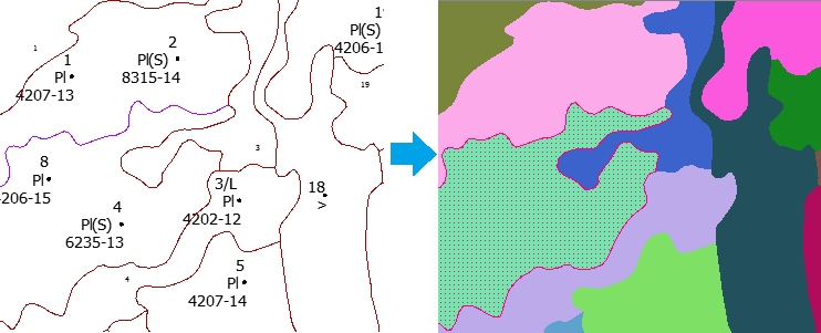
This example CAD-GIS translation has converted the linework of a design file into GIS polygons. Each polygon contains information from the CAD label points. The label can be used to get other attribute information using a database join.
Why is converting CAD to GIS so messy?
The main problem when converting from CAD to GIS is that we’re trying to fit a format with annotation and symbology into a format that does not support annotation and symbology.In a basic translation from CAD to GIS, we lose valuable information like text from the CAD dataset. This can be detrimental to data that relies on annotations to make sense – like blueprints, floor plans, and road design.
Turning the goo into a rainbow
 Like blending every colour to make a rainbow, haphazardly mixing data types won’t give you the output you expected. With a careful approach, I promise you can end up with the rainbow you always dreamed of.
Spatial ETLrequires manipulating data content and structure so it fits the requirements of the target system. Below is a four-part solution that ensures a successful CAD-to-GIS translation.
1. Validate your CAD data
Before trying to translate your CAD data to GIS, identify and solve issues that affect the data’s quality. Ensure it meets data model standards, and repair the geometry by snapping lines together.
2. Manipulate the CAD geometry
Transform the CAD data to make it fit your desired GIS data model. There arehundreds of transformationsyou can apply. This might include building areas out of CAD polylines, or splitting the CAD lines into different classes based on an attribute.
3. Represent CAD information in GIS attributes
The key to building GIS features from a CAD drawing is to find a way to preserve and represent the CAD information – including labels, text, blocks, dimensions, styles, and symbols. Annotations and symbology should be interpreted as attributes on the target GIS schema. Labels can be preserved by transferring them to the nearest line or polygon.
4. Georeferencing
CAD generally doesn’t have a notion of where it is (i.e., it’s not georeferenced). If this is the case, you should explicitly identify the CAD dataset’s coordinate system or change (reproject) it from a local grid.
![]()
集成数据类型给出了c的潜力reate datasets with a huge level of detail. Every data type – CAD, GIS, and otherwise – has its strengths. If we’re careful in our spatial ETL translations, we can take advantage of each strength in the palette of data types and blend them nicely together. Who knows, you might become theBob Rossof data integration.
What obstacles have you dealt with in CAD-GIS translations? What other CAD/GIS issues would you like us to delve into in a future post?
看:如何将DWG轴马力

Tiana Warner
Tiana is a Senior Marketing Specialist at Safe Software. Her background in computer programming and creative hobbies led her to be one of the main producers of creative content for Safe Software. Tiana spends her free time writing fantasy novels, riding her horse, and exploring nature with her rescue pup, Joey.